
ORVESTRA · WIKI
DSP - output limiter and speaker protection
IN
Selects input processing before the routing matrix.
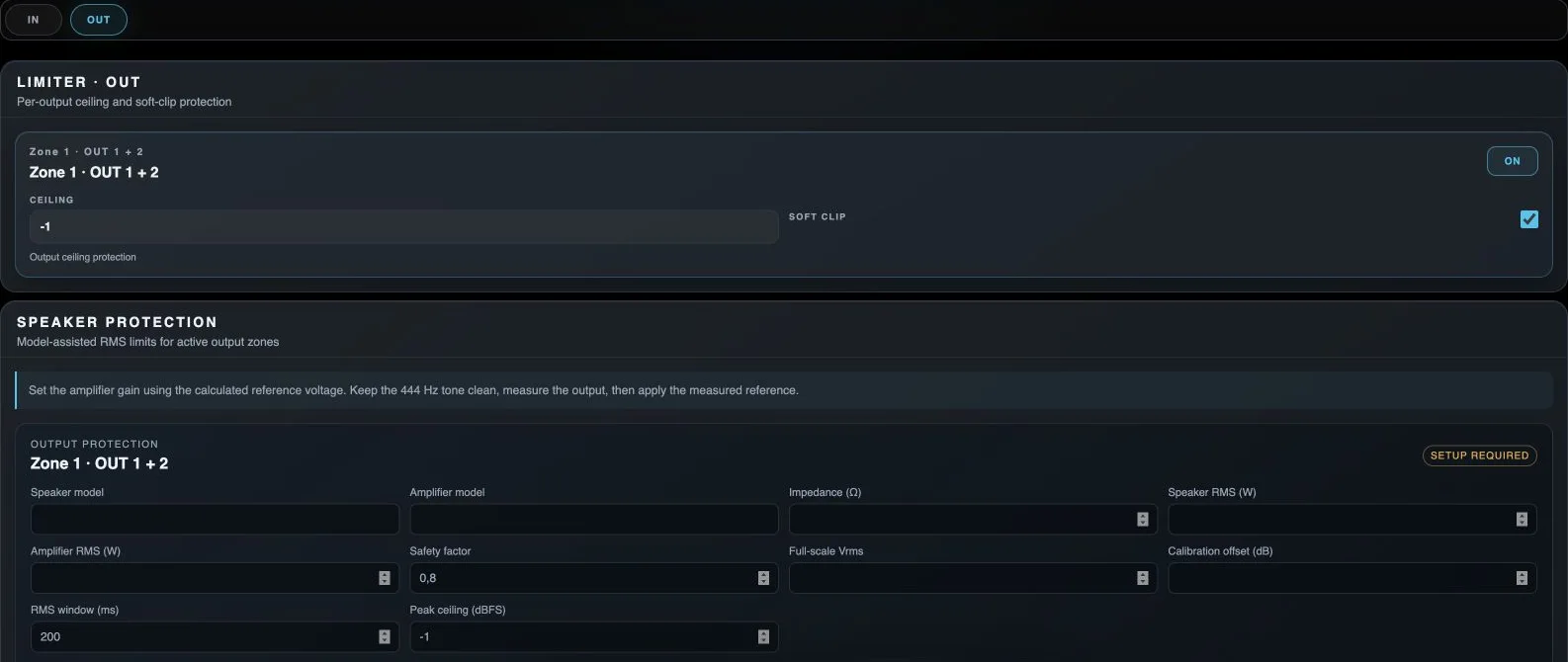
OUT
Selects physical-output processing after routing.
Processor On / Off
Enables or bypasses this processor on the indicated channel.
Limiter ceiling
Sets the upper signal limit protected by the limiter.
Soft clip
Enables softer peak clipping in the corresponding processor.
Speaker model
Descriptive loudspeaker model for the protection profile. The name does not replace impedance and power specifications.
Amplifier model
Descriptive amplifier model for the protection profile.
Impedance
Nominal load impedance used to calculate the safe output voltage.
Speaker RMS
Rated RMS loudspeaker power used in the safe-voltage calculation.
Amplifier RMS
Amplifier RMS power at the selected load. The calculation uses the lower of the available speaker and amplifier ratings.
Safety factor
Reduces the calculated permitted power to provide a safety margin.
Full-scale Vrms
Output voltage corresponding to digital full scale in the actual gain chain. Needed to convert a safe RMS voltage into a dBFS threshold.
Calibration offset
Additional calibration correction used to calculate the protection threshold.
RMS window
Averaging period for RMS protection.
Peak ceiling
Peak limit in the output protection profile.